Installing the Wallmount
For electricians. The Enua Wallmount is the wiring base that the Enua Charge / Charge E clips onto. It must be installed by a registered electrical installation company, following local, regional, and national low-voltage regulations.
Warning
Only qualified personnel may install, maintain, or repair this product. Do not install a damaged product, and do not install it in areas unsuitable for electrical installations or exposed to high temperatures (e.g. direct sunlight). Failure to follow the safety and installation instructions in the official manual voids the warranty. Repairs may only be performed by Enua or companies approved by Enua.
Before you start
You need:
- A Torx screwdriver or bits, T20 head, minimum 60 mm length
- A wire-stripping tool
- A smartphone with internet and the Enua Installer app, signed in to a registered Enua account
- The included accessory bag: 4× 4×40 mounting screws, 4× M4x12 cover screws, and 2× Enua cable grommets
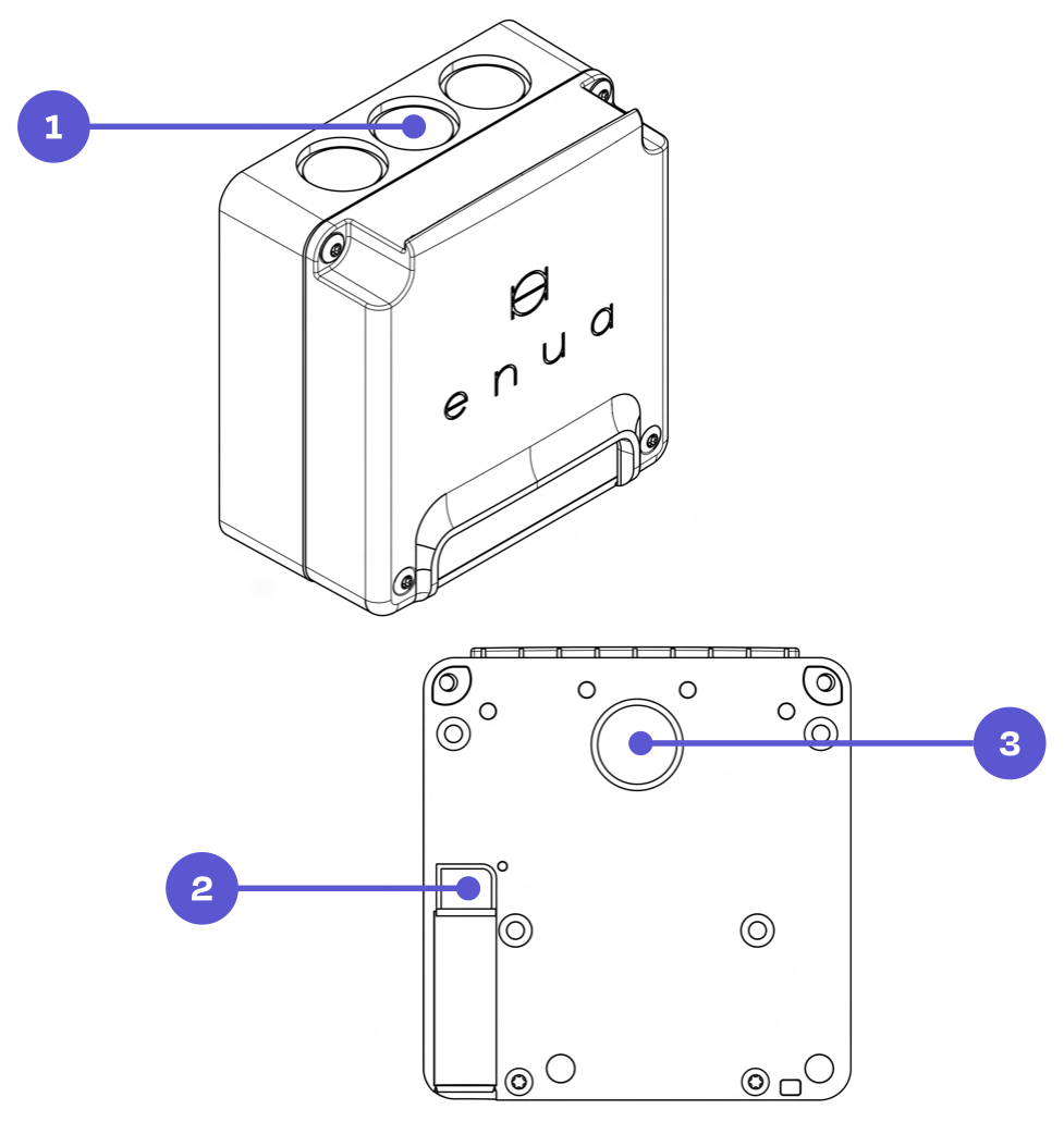
Plan the cabling. The Wallmount has five cable entries — three from the top, one at the bottom, and one from the back. Position the Wallmount to suit your intended cable route.
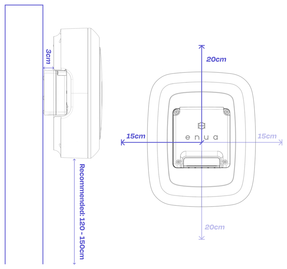
Mounting height. Enua recommends 120–150 cm from ground level, or 80–120 cm where accessibility requirements apply. Leave enough clearance around the unit to fit the Enua Charge / Charge E afterwards.
Note
National laws and regulations always take precedence and may specify a different installation height.
Power supply and daisy-chaining
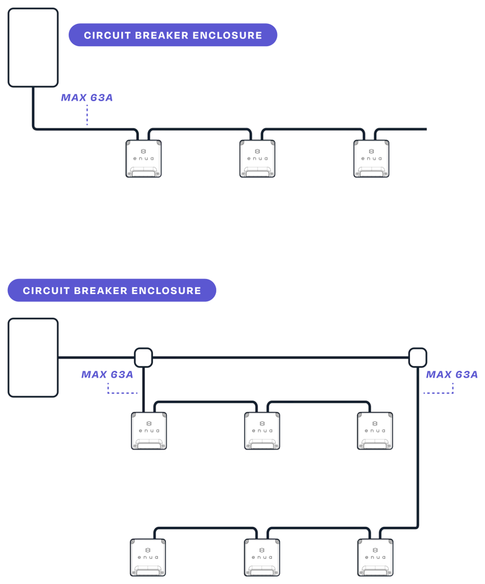
The Wallmount is designed for daisy-chaining. The maximum current draw through a single Wallmount is 63 A — when daisy-chaining, do not exceed this limit. Use a parallel connection if the circuit needs to carry higher amperage. Mount all phases in the same order as they come from the circuit breaker; there is no need to rotate phases manually.
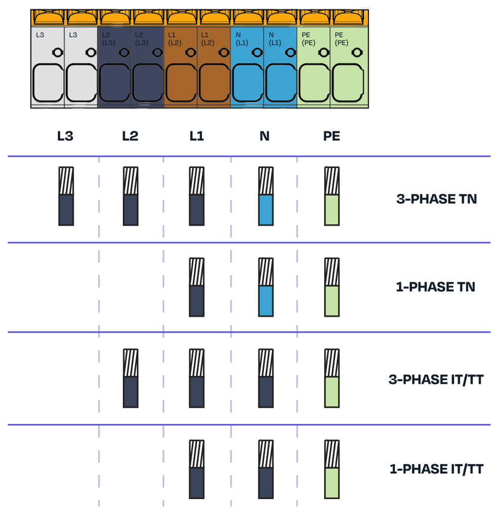
Supported grids: TN, IT, and TT, in both 1-phase and 3-phase (PE + N + L1/L2/L3).
Mounting
- Unbox the Wallmount, remove the front cover, and take out the accessory bag inside.
- Remove the blind plug(s) for the cable entries you will use.
- Fix the Wallmount to the wall vertically, using a spirit level. On a wooden surface, use the included mounting screws; on other surfaces, use mounting hardware suitable for the material. If you need to drill, print the hole pattern (last page of the official manual) at 1:1 as a guide.
Warning
Always make sure each cable grommet is fully mounted and sealing. Only the Enua cable grommet is approved — other grommets may void the warranty. Cable diameter must be 12–20 mm with the Enua grommet, and the maximum conductor size is 16 mm².
- Route and connect the cables. You can use single- or multi-stranded conductors; ferrules are not required.
- Fit the protective cover — this is mandatory. Without it, the product's degree of protection is not maintained and damage or injury may occur.
- Fit the front cover with the four supplied M4x12 screws, tightened to 3 Nm.
Connect each conductor according to your grid type:
Configure in the Enua Installer app
After mounting, program the Wallmount in the Enua Installer app. You set the main circuit breaker, the charging-circuit limit, the customer's address, optional Charge Point Operator / customer email / Wi-Fi, and an optional load-balancing meter; then scan the Wallmount's NFC tag (behind the Enua logo) or enter its serial number, set a per-Wallmount ampere limit (default 32 A), add any further Wallmounts on the circuit, and confirm and upload.
Note
In basements and areas with poor mobile reception, configure Wi-Fi during setup — the charging station needs Wi-Fi to connect there.
After uploading, the electrician receives an email summary, and the customer receives the registration code used to add the products in the Enua app. If you are setting up dynamic load balancing, its configuration begins right after upload.
Next steps
- Install the charger onto the configured Wallmount.
- Set up load balancing, if the facility requires it.
Maintenance
Clean with a damp cloth and no soap. Do not use running water, a garden hose, or a pressure washer. Inspect the product regularly; if you find damage or suspect a fault, do not use it — contact your retailer.
Common mistakes to avoid
A few installation errors come up again and again. Avoiding them keeps the charger seated correctly and the enclosure watertight.
Cable, grommet, or conduit too thick
Caution
Make sure that nothing blocks the charger from seating properly, as this will cause problems for the user when locking and un-locking the charger from the Wallmount.
- Use only the Enua grommet — other grommets are usually too large and will push the charger outwards.
- Keep the cable's outer diameter to 12–20 mm (20 mm max), else it will interfere with the charger.
- Don't run an oversized pipe or conduit into the entry.
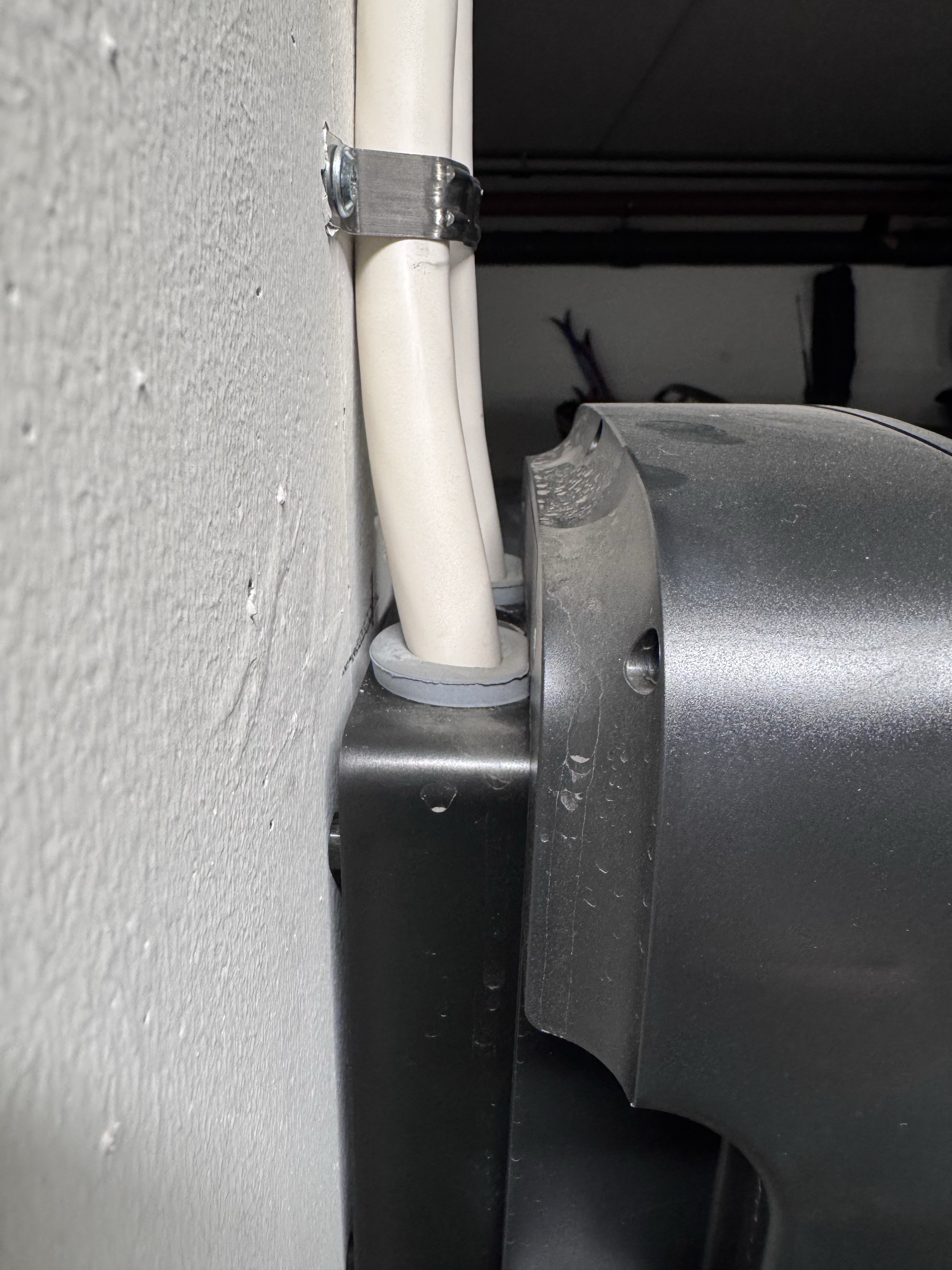
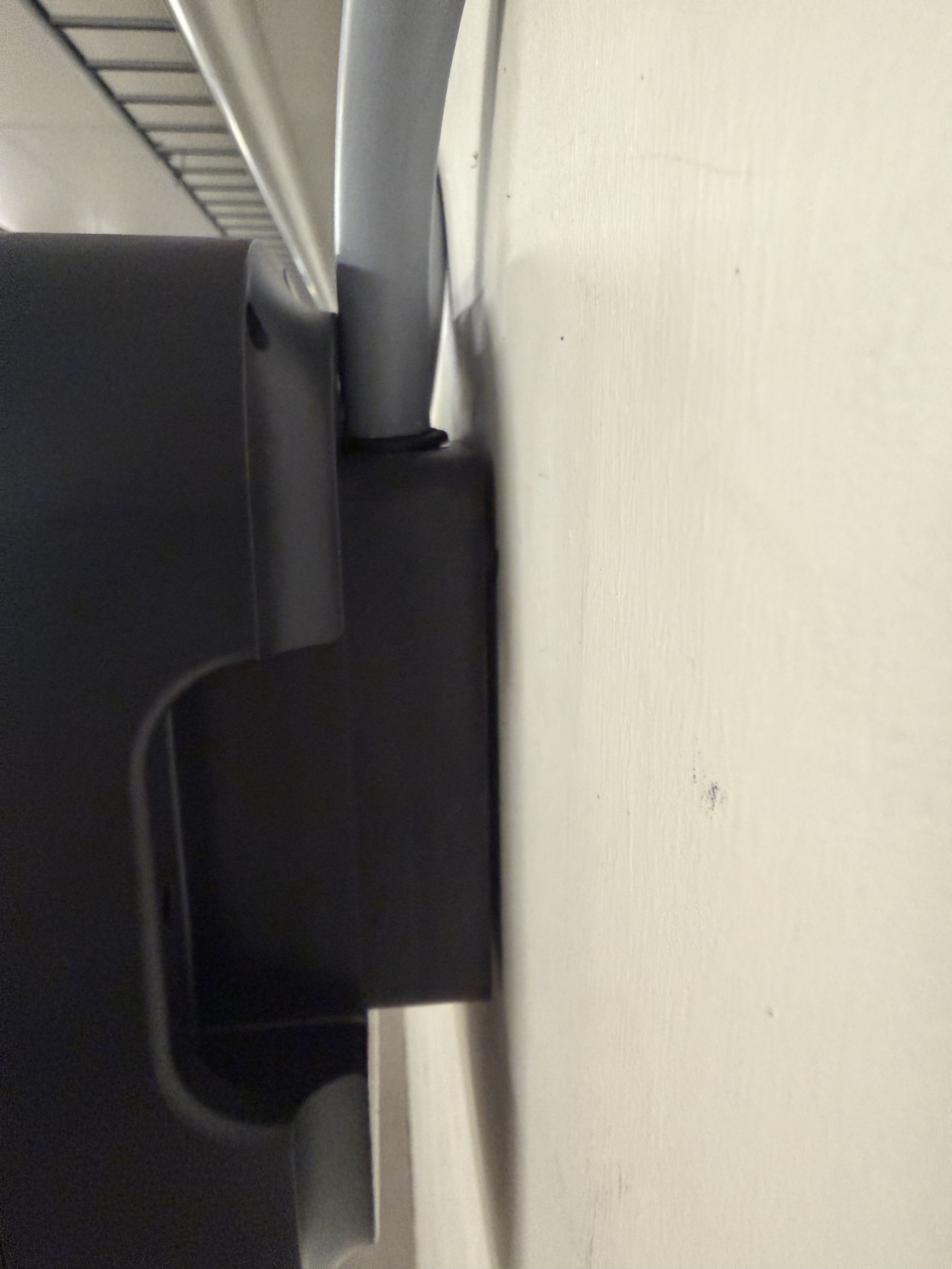
- Watch for non-original grommets — the usual culprit. They sit too proud, press on the back of the charger, and block the lock.
The images below shows a non-original grommet and a cable that's too thick. In both cases, the charger is pushed outwards.
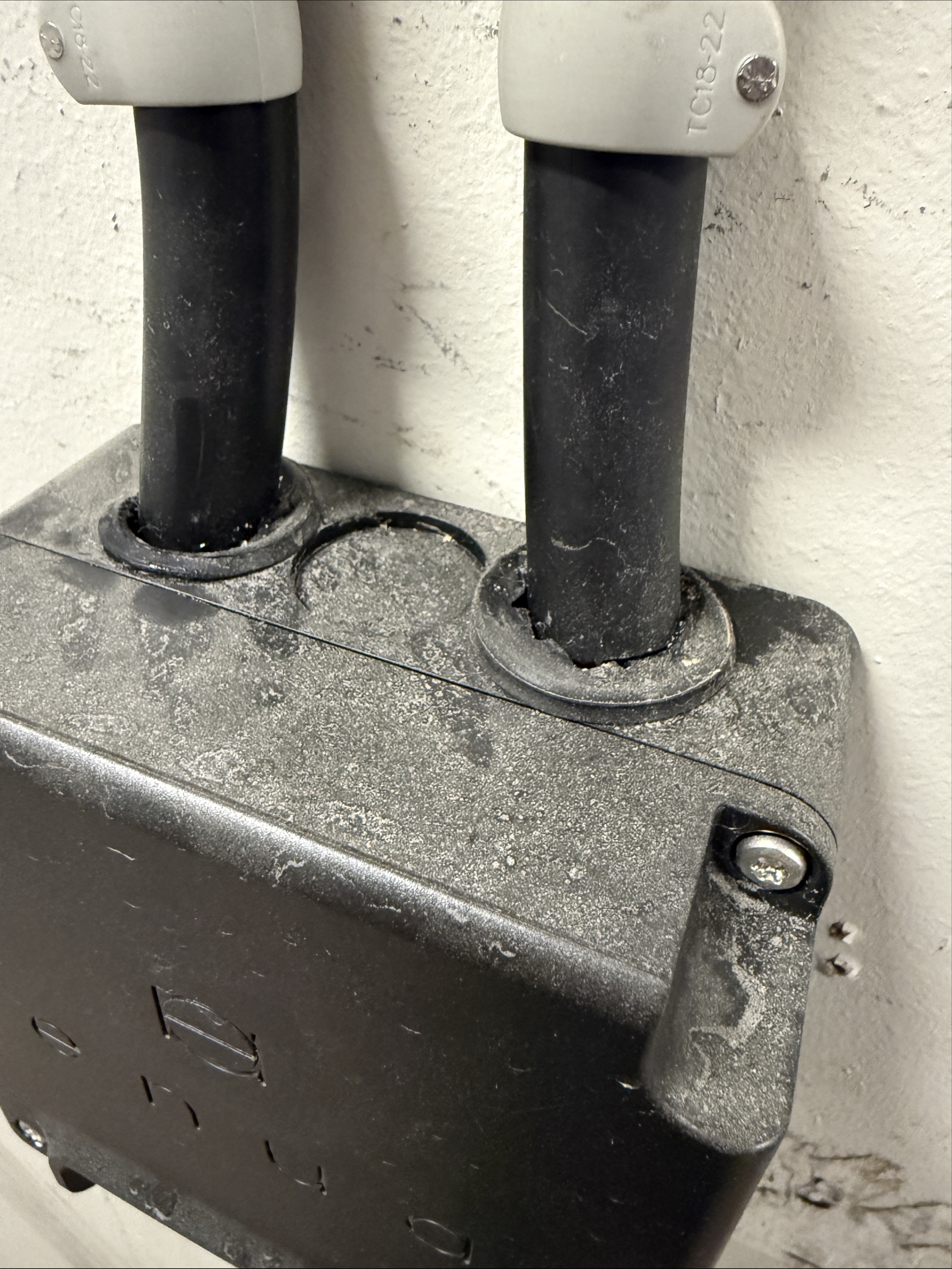
Cable grommet cut so it leaks
Caution
The Enua grommet only seals if you cut a round hole that fits tightly around the cable. A slit, an oversized hole, or an irregular cut lets water into the enclosure. Cut the smallest round opening the cable will pass through, so the grommet grips the cable all the way around.
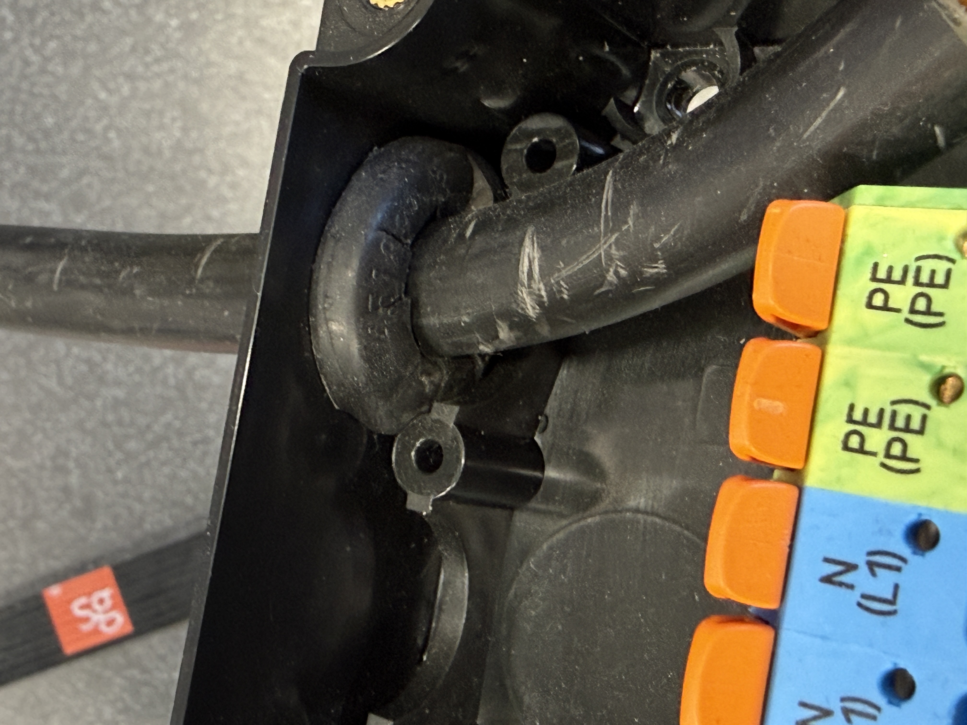
Forgetting the bottom entry on single installations
Caution
The Wallmount has a cable entry on the bottom (marked 2 below) that's easy to overlook. On a single, non-daisy-chained installation, punch out the blind plug and feed the cable in from below. Entering from the bottom stops water from running along the cable into the enclosure, giving a watertight installation.
Technical specifications
| Article number | 27003 |
| Weight | 0.70 kg |
| Protection | IP45 enclosure, IK10 impact, UV-resistant, UL94-V0 flame resistance |
| Dimensions (mm) | H 143 × W 135 × D 77 |
| Connection | TN / IT / TT grid; 1- and 3-phase (PE+N+L1/L2/L3); max 63 A |
| Cabling | 5 cable entries; wire diameter 12–20 mm (with Enua grommet); max 16 mm²; solid or stranded conductors, no ferrules |
| Mounting | 4 points, 5 mm holes |
| Material | PC, ASA, PA6 |
Full manual: Enua Wallmount installation manual (PDF). The PDF is the authoritative source — always follow it and applicable regulations.